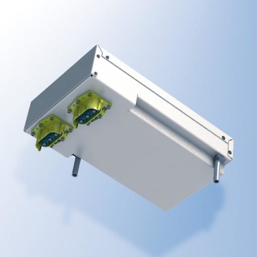
Electromotors with up to several kW and even MW of power consumption are used for almost all types of industrial drive technology. At constant speeds, their control technology is quite simple. However, it is often necessary to regulate the speed of the motors, which in turn makes everything more complicated.
Speed regulation in the larger power classes is realized with IGBT semiconductors. These can switch large loads using very low control powers. The necessary signals for IGBT control are transmitted with polymer optical fibres (POF) since very high insulation and voltage requirements must be met. The POF achieve disturbance-free and galvanically isolated signal transmission.
The connection to date between controller and driver board, i.e. the control and motor side, has been handled by individual fibres. The electro-optical conversion of the signals takes place in the transceivers of the circuit board, whereby optical contacts establish the connection to the fibres. Each optical fibre has a single connection on both the driver and the controller board, in which the transceivers are located. With this previous solution, all transmit and receive elements on the controller board require significant space, which makes the board unnecessarily large.
A further shortcoming is the mandatory correct positioning of the various POF fibres in the event of servicing or during installation, in order to ensure the individual connection between each driver and controller board. This assignment must be carried out with attention and requires a certain carefulness and time. Transmitter and receiver must not be mixed up if correct operation is to be ensured. In order to guarantee the quality of the fibre end surfaces, prefabricated cables are used which can also be installed on site by the customer.
Commonly used optical elements are developed for industrial use with wide temperature ranges and increased vibrations, but provide only simple strain relief for the fibres.
It is also important that the optical interface be consistently protected from dirt, and in an unplugged state protective flaps are even required. Cleanliness and correct connection are therefore the chief requirements – even with the at times numerous connections. This is expensive and non-service-friendly, in particular if a part of this transmission unit is damaged during operation and the entire board has to be replaced.
The solution for automation
In order to solve these problems, HARTING has developed a transmission principle which involves relocating the transceivers of the controller board into a pluggable module and thus integrates the optical interface according to the principle of "electrical plugging and optical transmission".
HARTING uses solutions from the Han-Eco® 10A series in automation for electrical plugging and as a system housing. The Han® housing fulfils the increased requirements of the automation market and integrates optimal kink protection and strain relief for the fibres.
In addition, the printed circuit board in the Han® housing can accommodate series resistors and supporting capacitors if required, in order to control the optical elements without error and prevent interference. The electrical contacts of the electrically connecting D-Sub mating face also resist wear caused by microvibrations and rougher shocks.
You find further information here: https://www.sps.harting.com/
You find the press information here: http://www.harting.com/en/news/pressfolder/sps
HARTING Stiftung & Co. KG
Marienwerderstr. 3
32339 Espelkamp
Telefon: +49 (5772) 47-0
Telefax: +49 (5772) 47-400
http://www.HARTING.com
Referent Presse- und Öffentlichkeitsarbeit
Telefon: +49 (5772) 47-1744
Fax: +49 (5772) 47-400
E-Mail: michael.klose@harting.com
Zentralbereichsleiter Publizistik und Kommunikation
Telefon: +49 (5772) 47-244
Fax: +49 (5772) 47-400
E-Mail: Detlef.Sieverdingbeck@HARTING.com


